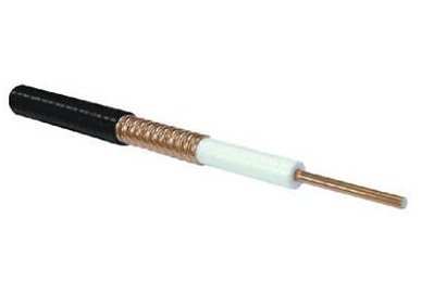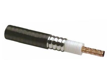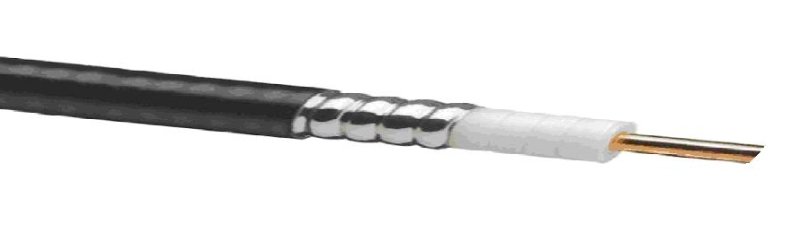

Leaky coaxial cable 1 5/8″, radiation mode, FRNC Jacket
Material
| Component | Specification |
|---|---|
| Inner Conductor | Helical Copper Tube |
| Dielectric | Foam PE |
| Outer Conductor | Copper foil |
| Jacket | Flame retardant polyolefin, Black, Halogen free |
Mechanical Data
| Parameter | Value |
|---|---|
| Cable Dimension (inch) | 1 5/8 |
| Tensile Strength (N) | 3000 |
| Min. Bending Radius – Single bend (mm) | 500 |
| Min. Bending Radius – Multiple bend (mm) | 700 |
| Minimum Distance to Wall (mm) | 50 |
| Recommended Hanger Spacing (m) | 0.8 to 1.2 |
Electrical Data
| Parameter | Value |
|---|---|
| Impedance (Ω) | 50 |
| Relative Velocity of Propagation (%) | 89 |
| Capacitance (pF/m) | 75 |
| Insulation Resistance (MΩ x km) | ≥5000 |
| Insulation Voltage (V) | 15000 |
| Jacket Spark Test Voltage (V) | 10000 |
| Operating Frequency Band | 75MHz to 2700 MHz |
| Optimum Operating Frequency Band | 700MHz to 2700MHz |
| Stop Band | 1110~1140 MHz & 2220~2280 MHz |
VSWR Specifications
| Frequency Range | VSWR |
|---|---|
| 75 MHz to 150 MHz | ≤ 1.3 |
| 450MHz to 500MHz | ≤ 1.3 |
| 800MHz to 960MHz | ≤ 1.3 |
| 1700MHz to 2025MHz | ≤ 1.3 |
| 2110MHz to 2170MHz | ≤ 1.3 |
| 2300MHz to 2700MHz | ≤ 1.3 |
Performance Data
| Frequency (MHz) | Attenuation (dB/100m) | Coupling loss 2m dB (50%) | Coupling loss 2m dB (95%) |
|---|---|---|---|
| 75 | 0.60 | 70 | 79 |
| 100 | 0.70 | 70 | 81 |
| 150 | 0.94 | 78 | 90 |
| 450 | 1.50 | 81 | 90 |
| 500 | 1.60 | 82 | 90 |
| 700 | 1.90 | 74 | 77 |
| 800 | 2.10 | 70 | 73 |
| 900 | 2.30 | 69 | 72 |
| 960 | 2.40 | 69 | 71 |
| 1700 | 3.30 | 69 | 72 |
| 1800 | 3.60 | 64 | 67 |
| 1900 | 3.90 | 63 | 66 |
| 2000 | 4.10 | 63 | 66 |
| 2100 | 4.30 | 62 | 65 |
| 2200 | 4.50 | 62 | 66 |
| 2400 | 5.00 | 61 | 65 |
| 2600 | 5.60 | 62 | 64 |
| 2620 | 5.80 | 62 | 65 |
| 2700 | 6.20 | 63 | 66 |
Remarks
Standard Conditions and Test Methods:
- Attenuation at ambient temperature 20°C
- Average power at ambient temperature 40°C and inner conductor temperature 100°C
- Attenuation Test Method: IEC 61196-4
- Attenuation Tolerance: ±5%
- Coupling Loss Test Method: IEC 61196-4
- Coupling Loss Tolerance: ±5 dB